views
Installing the Extension Box
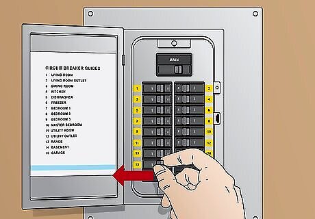
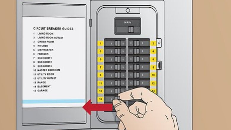
Turn off the electricity to the garage. Find the circuit breaker or fuse box, which will be in the basement or bottom floor of your home. Flip the switch for the garage. To test for an electrical current, plug a radio or lamp into a wall outlet in the garage. If the power is off, the device won’t turn on.
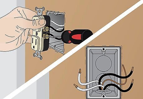
Unscrew a wall outlet near the garage door. Pick an outlet as close to the door as possible to make installing the floodlights easier. Use a screwdriver to loosen the outlet. Remove the screws on the sides of the outlet to free the wires. Leave the electrical box containing the wires in the wall.
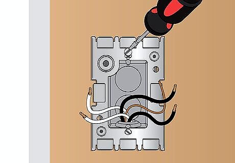
Screw a metal mounting plate over the electrical box. Visit a home improvement store to purchase an extension box that is the same shape as the outlet. The mounting plate will be included. Fit the plate around the electrical box and, using the included screws, fasten it to the wall.
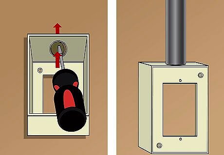
Attach a metal conduit connector to the extension box. First, look for a circle, also called a knock-out plug, on the top surface of the extension box. Use the tip of your screwdriver to pry the plug up and away. Then position a ⁄2 in (1.3 cm) metal conduit connector on top of the hole. The metal conduit connector, along with other conduit pieces, can be found at most home improvement stores.
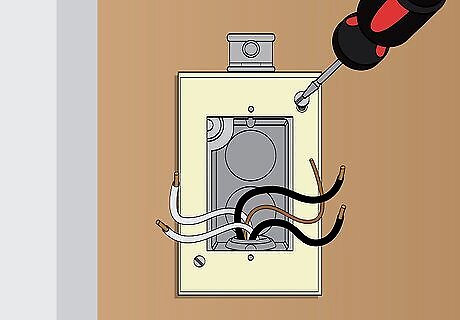
Screw the extension box to the mounting plate. The extension box will come with 2 long screws. Position the extension box on the plate with the conduit connector facing upwards. Line up the holes on the box and plate, then use the screws to fasten them together.
Connecting the Conduit Tubing
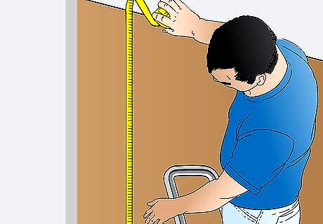
Measure from the extension box to the garage ceiling. Get out a stepladder and tape measure. Start measuring from the top of the box itself, not the conduit connector. Once you have a number, subtract 1 ⁄2 in (3.8 cm) from it so the conduit won’t be right up against the ceiling later.
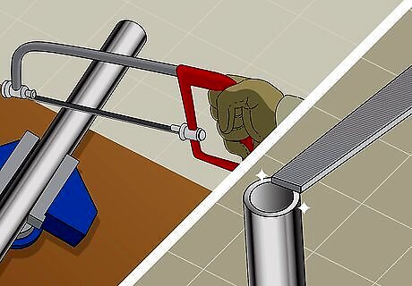
Saw a piece of conduit to size. The conduit is made from electrical metallic tubing or EMT, which can be purchased cheaply from home improvement stores. Using a hacksaw, cut the tubing to the length you need. Use a file to smooth over any sharp edges you notice. To get a rough estimate of how much EMT you will need, measure up to the ceiling, then measure to the center of the garage door. Add the 2 measurements together.
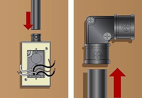
Connect the conduit tube to the extension box. Place a right-angle conduit connector on one end of the tube. Slide the tube’s free end over the metal connector on top of the extension box.
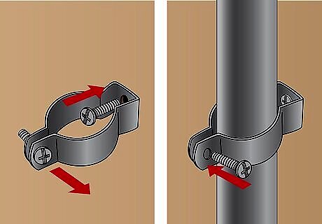
Place a conduit hanger to hold the tube to the wall. Undo the screw holding the hanger’s prongs together. Halfway up the conduit tube, put the hanger’s prongs around it. Position the hanger so it is between the wall and the tube. Connect the hanger’s prongs with the screw you removed earlier. Then place a #10 or 5 mm screw in the hole on the hanger’s other end to secure it to the wall. Keep the conduit tube as vertically straight as possible before securing it to the hanger. Check this by looking up and readjusting it. Use a magnetic torpedo level to get it perfect.
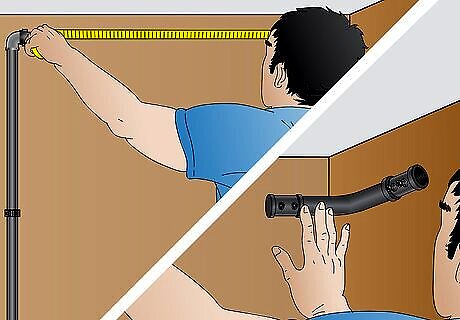
Measure from the right-angle connector to the wall corner. Use the tape measure to gauge how much conduit tubing you’ll need to reach the corner. Hold a conduit elbow connector in the corner near the door. You will need to connect it to the right-angle connector with the tubing.
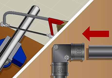
Cut the tubing and place it on the right-angle connector. Saw the tubing like you did before. Climb up on the ladder and slide the tubing into the free end of the right-angle connector. The tube should reach the wall corner near the door.
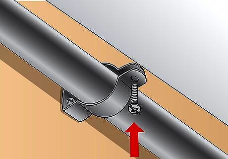
Install a conduit hanger if the tubing is long. If the tubing is longer than 12 in (30 cm), secure it with a hanger. Place the hanger about halfway along the tube. Hold the tube between the hanger’s prongs and screw the hanger to the wall like you did earlier.
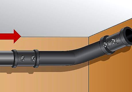
Add an elbow connector to the end of the conduit. The elbow connector is a bent connector. It should be placed in the corner of the garage’s side and front wall. Slide it over the end of the conduit and angle the other end towards the garage door.
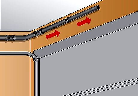
Continue hanging tubing until you reach the center of the garage door. Measure from the elbow connector to the center of the garage door and cut more tubing as needed. Build the conduit, placing the tubes above the garage door. Hold the tubing to the wall by placing a hanger every 12 in (30 cm). To find out exactly where the center of the door is, measure the length of the door.
Placing the Junction Box and Outlet Box
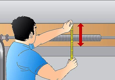
Measure from the top of the garage door to the ceiling. Stay inside the garage to do this. Climb up on a ladder and use the tape measure to take the measurement. Subtract 1 in (2.5 cm) to get the measurement you will use later.
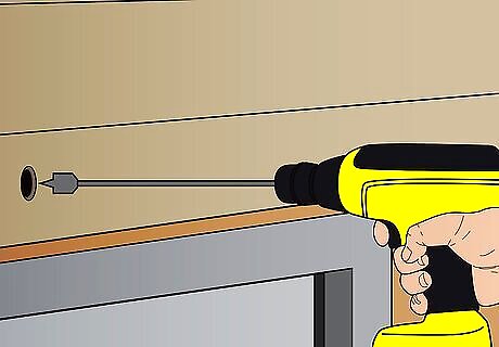
Mark the measurement on the outside and drill a hole through it. Set the ladder outside and measure up from the top edge of the door. Use a ⁄8 in (22 mm) spade drill bit to create a hole in the garage wall.
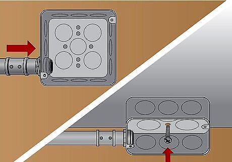
Screw a junction box to the garage ceiling. Go back inside the garage. Fit a junction box over the end of the conduit tubing. You will need to use a screwdriver to pry off a knock-out plug. Use the screws included, usually #6 or 3.5 mm screws, to fasten the box to the ceiling.
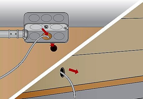
Run a 14/2 nonmetallic cable through the junction box. Pick up a 14/2 nonmetallic Romex cable from the home improvement store. It will have the 14/2 rating on the label. Push it into the junction box through the hole to the outside. Leave it hanging there for now.
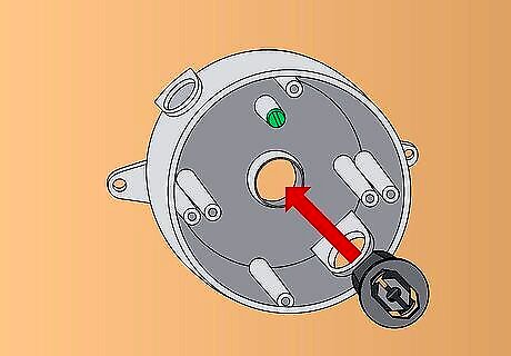
Push a cable connector through the hole in a round outlet box. You will also need a round outlet box and a plastic cable connector from the home improvement store. Find the hole in the back of the outlet box and push the cable connector into it.
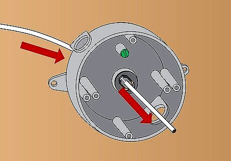
Feed the nonmetallic cable through the connector. Grasp the end of the cable and push it through the connector. Use your screwdriver to tighten the screw on the connector, holding the cable in place.
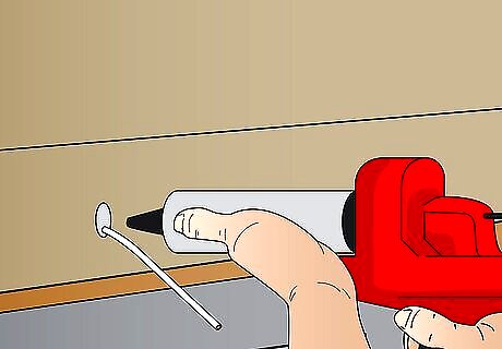
Fill the hole in the garage with silicone caulk. Silicone caulk or a weather-resistant putty work well for patching up the hole. With a caulk gun, shoot the caulk into the hole until it is filled. Use a damp cloth or finger to smooth the caulk.
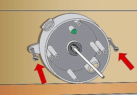
Screw the outlet box to the garage. Press the outlet box against the garage. It should rest flat against the caulk. Place 2 in (5.1 cm) decking screws in the holes around the box to secure it in place.
Completing the Electrical Circuit
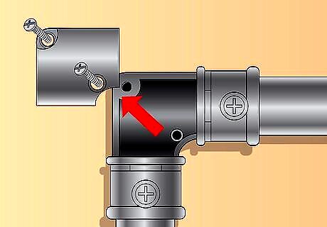
Remove the cover plate from the right-angle connector. The right-angle connector you want to adjust is the one closest to the extension box. It should be at the top of the first conduit tube you secured to the wall. Undo the screws on the connector’s surface to remove the cover plate.
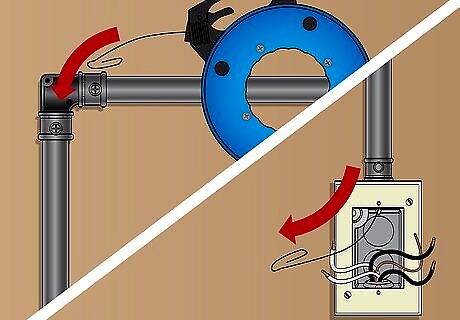
Push electrician’s fish tape down into the extension box. Fish tape is a hook on a cord rather than tape and it is used to pull wires through tight spaces. Unspool the tape from the reel and lower the hook through the conduit tubing until it emerges from the extension box. Fish tape, along with electrician’s tape and copper wires, can be found at any hardware store.
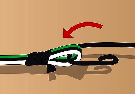
Tape copper wires to the fish tape. You will need 1 strand of white, black, and green 14-gauge stranded copper wire. Use electrician’s tape to bind the ends of the wires to the fish tape.
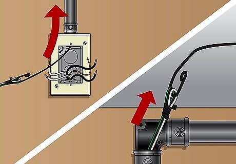
Pull the wires up to the right-angle connector. Go back to the right-angle connector. Pull the fish tape out of it to raise the wires up to you. Pull the wires far enough out of the connector so they won’t fall back down. Take off the electrical tape to remove the fish tape.
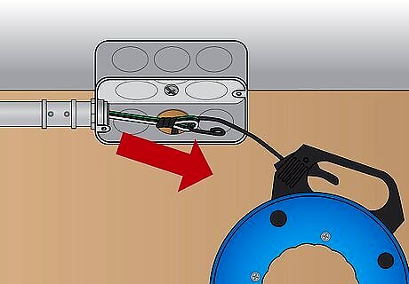
Use the fish tape to pull the wires through the junction box. Go to the junction box, which is above the garage door, and feed the fish tape through it. At the right-angle connector, pull out the fish tape and fasten the wires to it again. Pull the wires through the conduit tubes to the junction box.

Assemble the floodlights according to the owner’s manual. Follow the directions to assemble the lights. Typically you will twist the lights into the holes on the mount by hand. The lights won’t be completely tightened until you finish hanging them later.
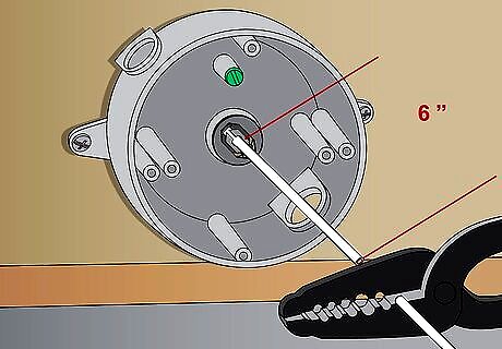
Trim the cable at the outlet box. At the outlet box on the outside of the garage, pull the cable out a little and measure it using the tape measure. Leave about 6 in (15 cm) of wire exposed. Cut the wire to length using wire cutters or pliers.
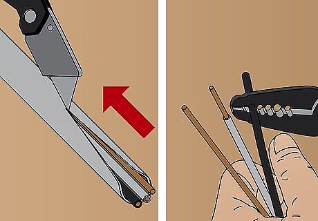
Strip the insulation from the wires. First, use a utility knife to gently remove the plastic sheathing around the wires. Then use wire strippers to expose ⁄2 in (1.3 cm) of the black and white wires.
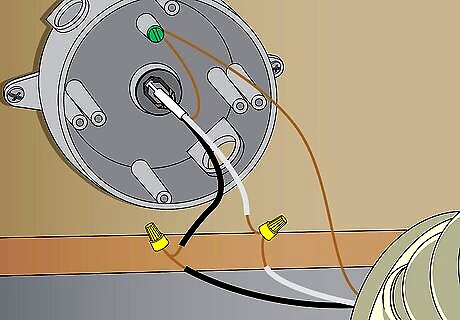
Join the cables to the flood lights. If the flood light wires aren’t already exposed, strip them as well. Hold the same-color wires together. Use pliers to twist the wires clockwise, wrapping them together. Place a wire nut over each connection and wrap it in electrical tape to be safe. The electrical work can be the trickiest part. If you feel unsure about doing it, call a professional.
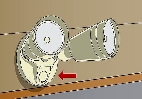
Attach the floodlights to the wall. Follow the instructions in the owner’s manual to do this properly. The floodlights will come with machine screws that you can use to mount them to the wall. Place the bulbs in the lights.
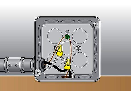
Connect the wires at the junction box. At the junction box, you should have the Romex cable and the colored wires you pulled up with the fish tape earlier. Cut the Romex cable to size, then strip all the wires and connect the matching colors. Secure the wires with wire nuts and tape.
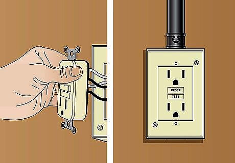
Connect a switch to the extension box. First, purchase an inexpensive GFCI receptacle switch. Back at the wall outlet, connect the wires to the correct plugs. Line up the holes on the switch with the extension box and use the included screws to secure it in place. Turn on the electricity and test your new lights! Switches often use ⁄16 in (0.79 cm) screws, although this varies depending on the size of the switch.









Comments
0 comment