
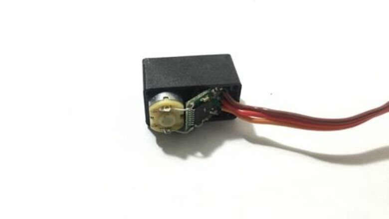
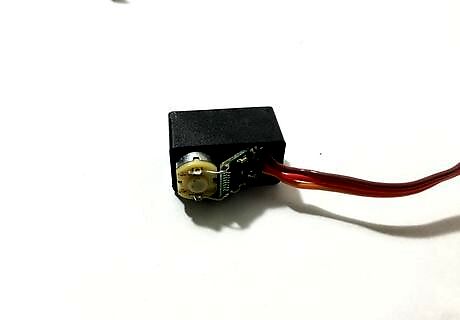
Open up the servo. Unscrew the screws at the base of the servo. Make sure to use an appropriate screw driver, often size #00. Keep the servo flat on the table and handle with care. Picking it up could cause the front side to fall off, spilling gears. Don’t take out the gears unless you’re sure you can reverse engineer and put them back.
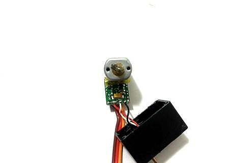
Identify the variable resistor (trimpot). This is the resistor with three pins, and wires leading from it to the circuit board. This variable resistor is also called the servo trimpot. Occasionally, this resistor is attached to the circuit board, rather than a separate component.
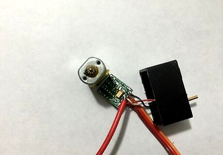
Solder a wire to the wiper wire. Solder a wire to the analog signal pin of the trimpot. This is almost always the central pin of the trimpot. See Tips for a way to confirm this. Avoid soldering the other pins. If you accidentally make the wrong connection, remove the solder and try again.
Screw the servo back together. You will need to make room for the extra wire that you added. Try cutting a notch in the cover with a pair of wire cutters. Take care not to let the gears fall out during this step.
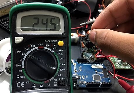
Measure the servo's voltage with a multimeter. Set a multimeter to voltage mode. Power your servo using a 5V supply. To measure the servo's voltage, connect the positive probe of the multimeter to the analog wire that you soldered on the servo. Connect the negative probe to the ground pin. Now you should be getting readings. Experiment and turn the servos head to see the readings change. The voltage reading is based on the resistance set by the trimpot. With a little experimentation, you can use this output to represent the direction the servo is facing direction.


Comments
0 comment